MicroAI AtomML+™ How-To#
To start monitoring devices on your MPU device you must first register it on MicroAI Launchapd. This is where you will set up your device profile and configure the setting your need to perfectly tune your AI model for the project at hand.
Log into your Launchpad account. You should have already set up an account in the “Getting Started” portion of this documentation. IF you have not set up a Launchpad account please go do so.
After logging in, you can add a profile directly from the Launchpad home page. In the bottom right you will see a button that says “ADD PROFILE”, clicking on this button will open up a page to add your device profile.
On the first page of creating a device profile you will first put in a profile name. this name can be whatever you want but it is recommended to make it unique and easily recognizable.
Then choose your use case and technology, for the purposes of this tutorial we recommend choosing Asset Performance Monitoring(APM) as the use case and AtomML+™ as the technology. If you want to use a different use case then please go to that use case tutorial.
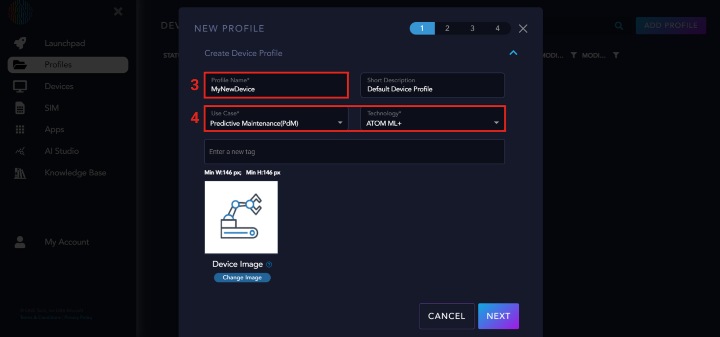
Next, you will click “NEXT” in the bottom right and it will change to a new page. At the top of the page you will see several headers titled “Channels”, “Health Groups”, AI Generals”, and “Y Code”. These are the inputs needed to configure AtomML+™ to the custom parameters your want to train your MicroAI Model on.
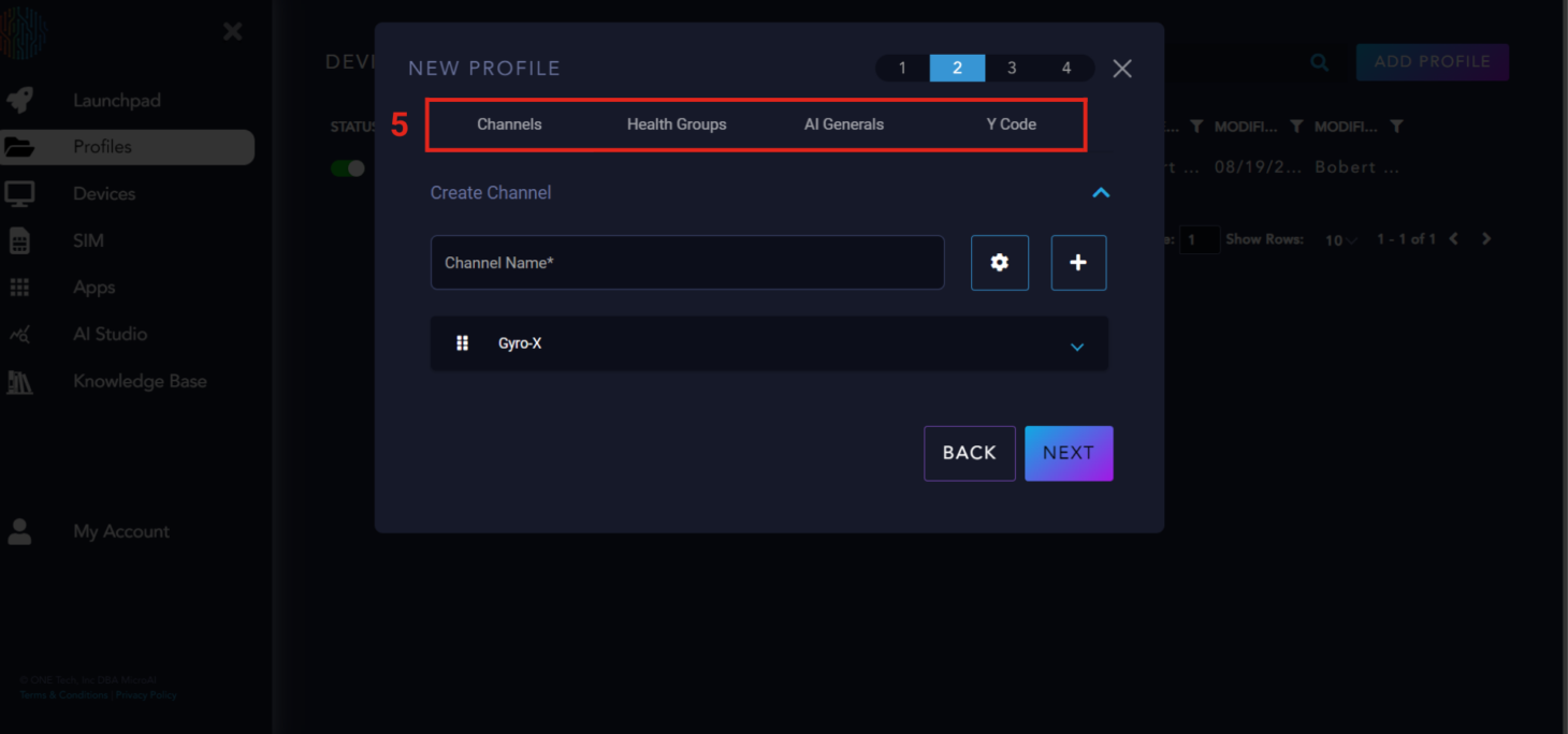
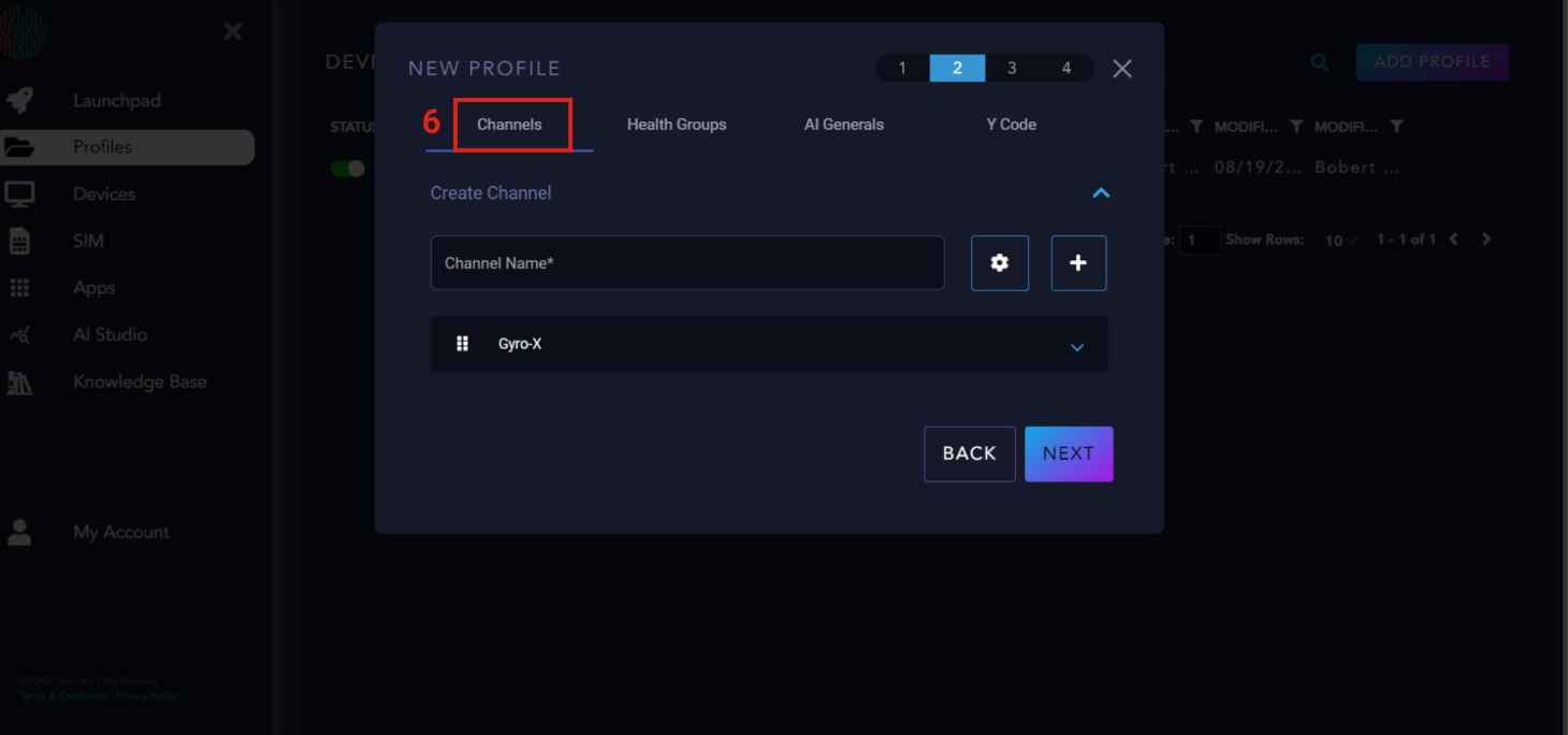
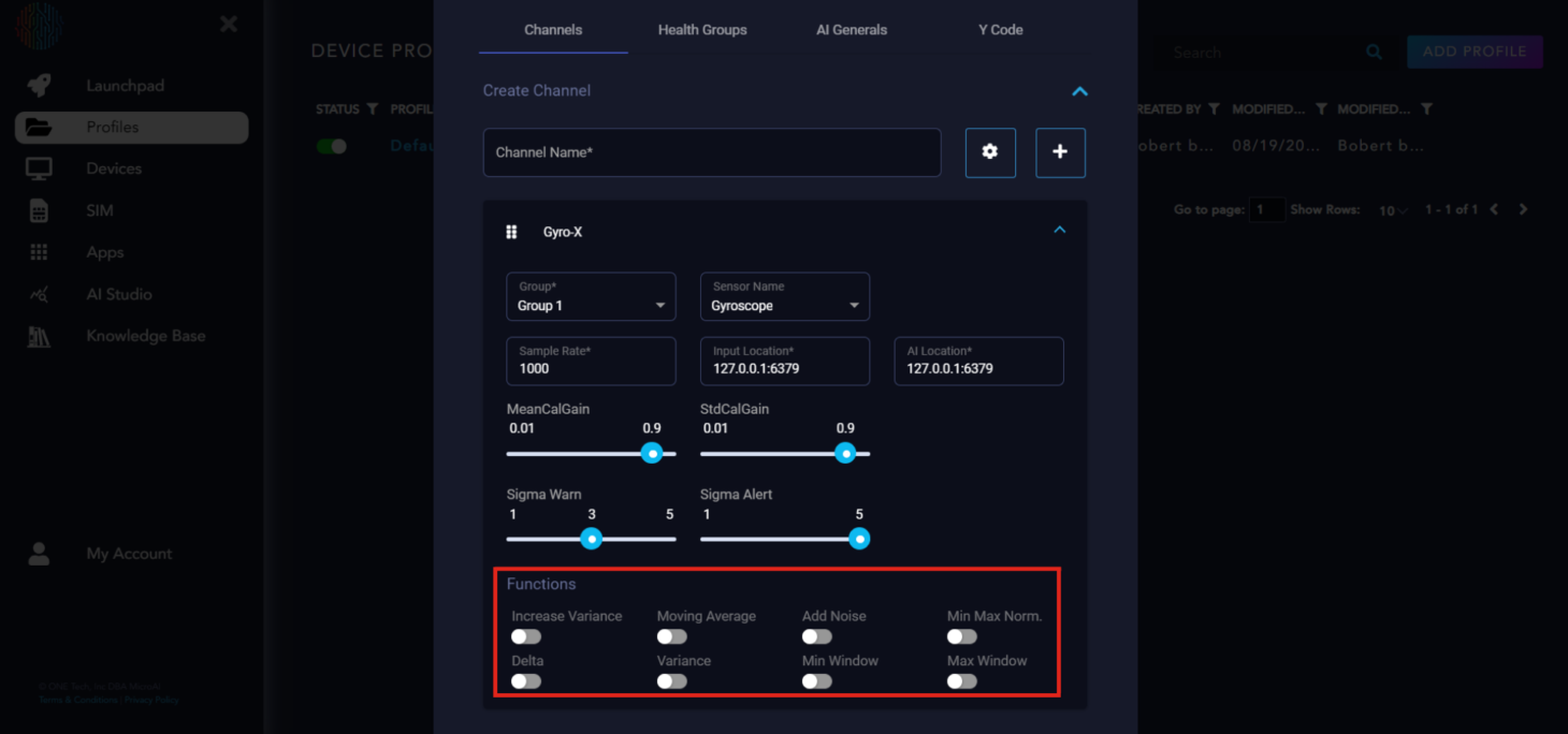
Lets go over channels first. The channels are essentially the data sources, Once you have created a channel or multiple channels there is a drop down which allows for more decriptive tuning for each channel.
Channel Parameter Explanation#
With the AtomML+™, you can configure multiple health groups of channels for monitoring. For now, let’s focus on using one group.
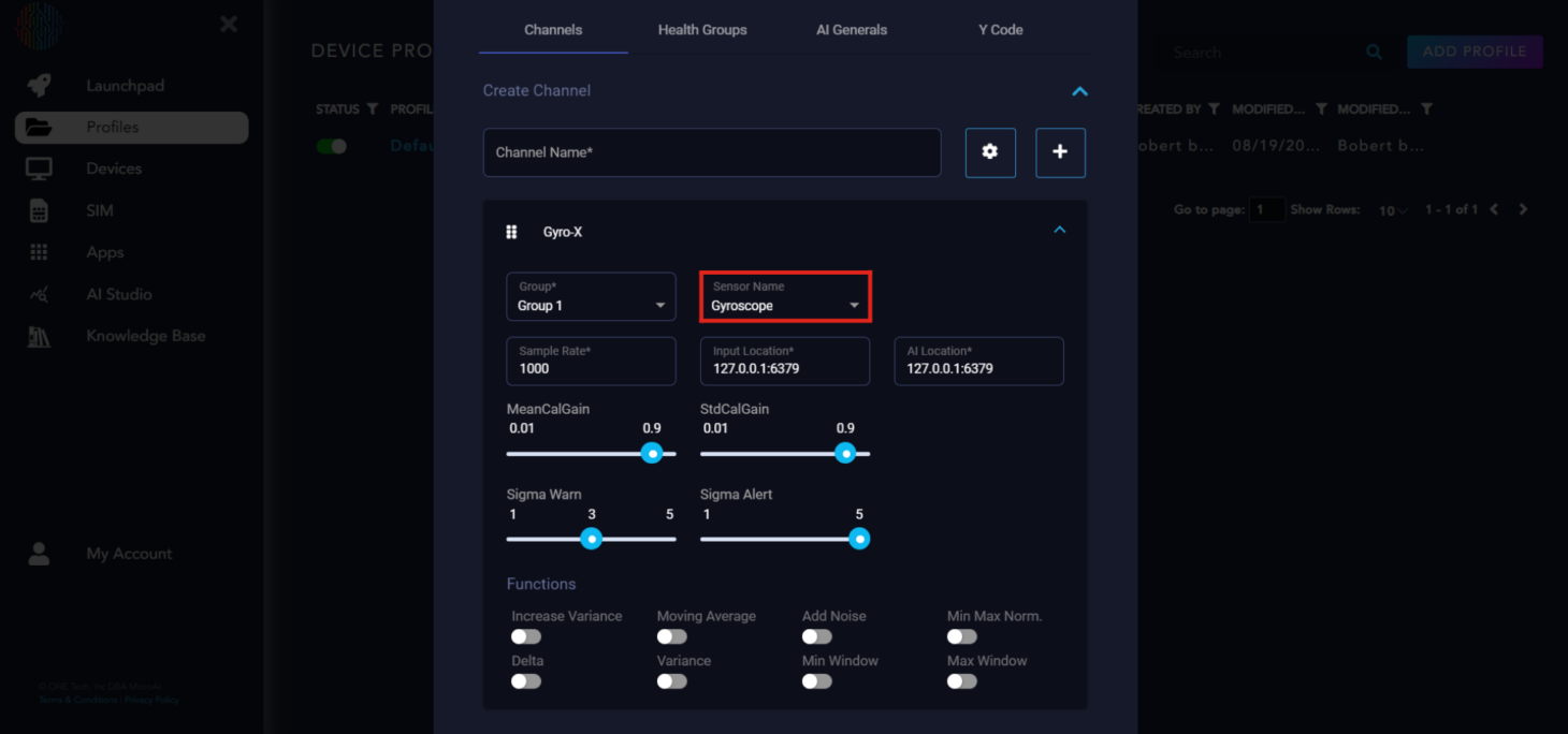
The first box is the health group it is assigned to.
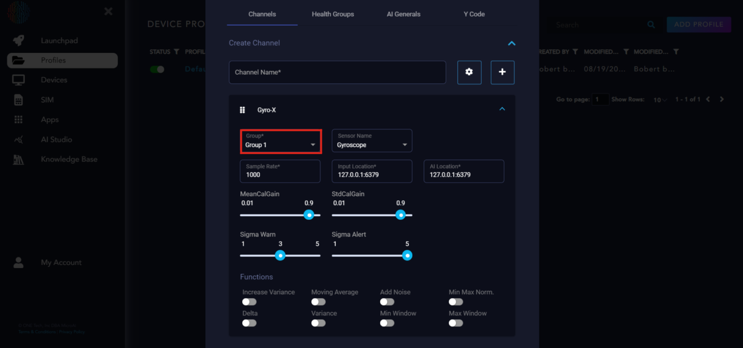
Next is sensor name. This is the type of sensor the channel is. There are many preloaded sensor names, but if your sensor is not available, you can type it in the box and add it as a sensor.
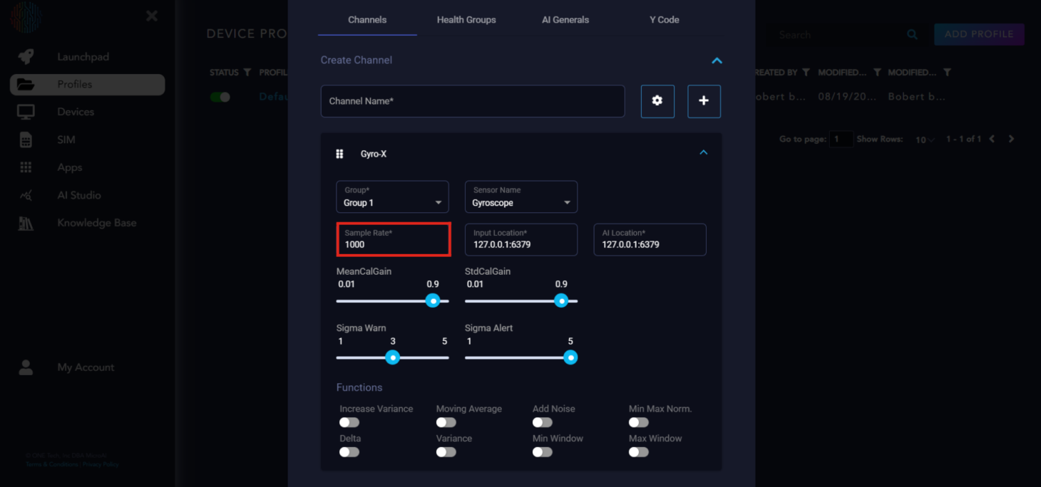
Next is the sample rate, which is how many samples are taken in one second. It takes the continuous data and discretizes it. The higher the sample rate, the more similar it will appear to the actual continuous data. Keep this in mind for low memory edge devices. For now, let’s keep it at 1000.
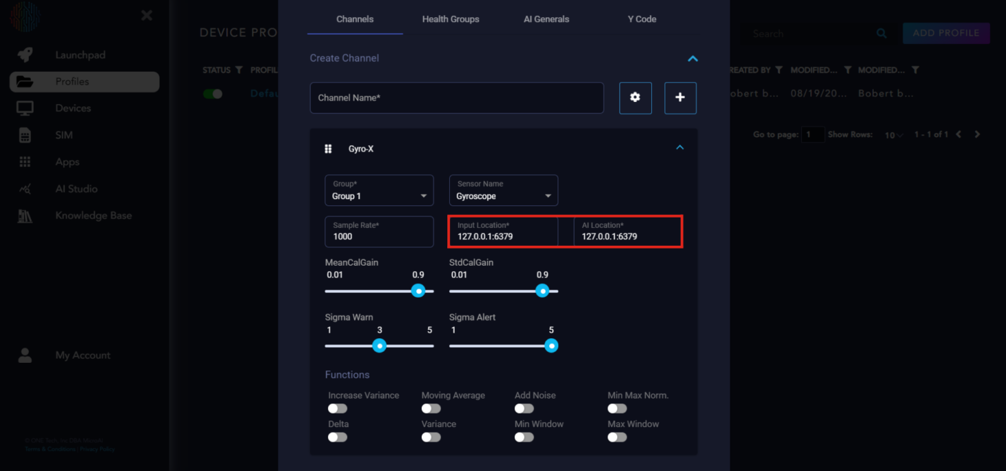
The next two boxes are simply the IP addresses of where you can input data and where the AI Location is. We do not need to change these for our purposes.
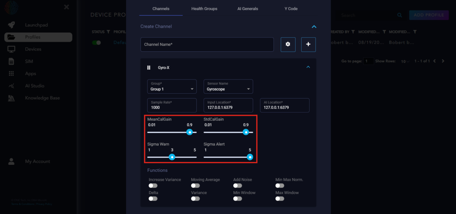
The sliders you see are parameters that can be tuned to affect bound calculations.
MeanCalGain: Filter coefficient to approximate mean. Higher values lead to more stable bound widths.
StdCalGain: Filter coefficient to approximate standard deviation. Lower values lead to more stable bound widths.
SigmaWarn: Number of standard deviations away to set the upper and lower bound from the one step ahead prediction, used for abnormal classification.
SigmaAlert: Number of standard deviations away to set upper and lower thresholds for alert generation.
The buttons on the bottom are built-in feature engineering functions you can turn on or off at your discretion. We recommend starting off with no feature engineering and seeing the results, then coming back to turn on the functions which will give you the results you want.
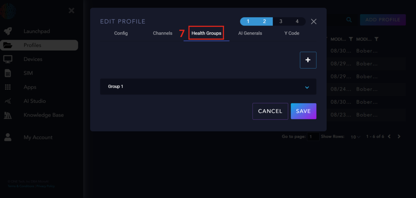
Health Groups#
Next are the Health Groups. You can add multiple health groups and assign different channels to each group for monitoring. The health groups control the health score, which is what you will see once a device has been registered and is sending data to Launchpad. It’s recommended to start with one health group and add more later if needed.
What is the Health Score?#
Health Score is a flexible metric that reflects the likelihood of a break occurrence at the machine. It combines the density, magnitude, and long-term effect of abnormalities.
Health Group Parameter Explanation#
With the expandable section “Health Group Parameter Explanation,” let’s delve into the various parameters and their functions:
Hysteresis 1 and 2 control the speed at which a health score increases. The larger the value, the slower the increase. All values over 1 cause the health score to increase slower than it decreases.
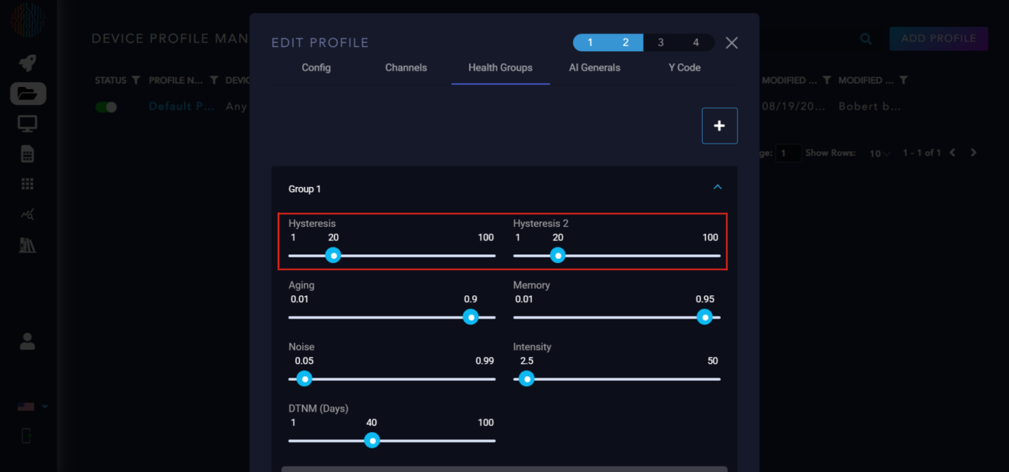
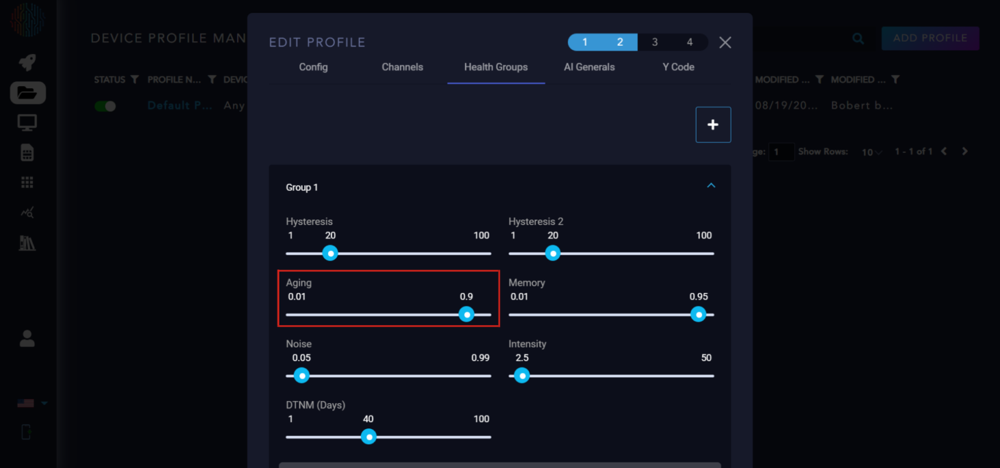
Aging: controls the rate of change in the health score (0,1). The higher it is, the less the rate of change.
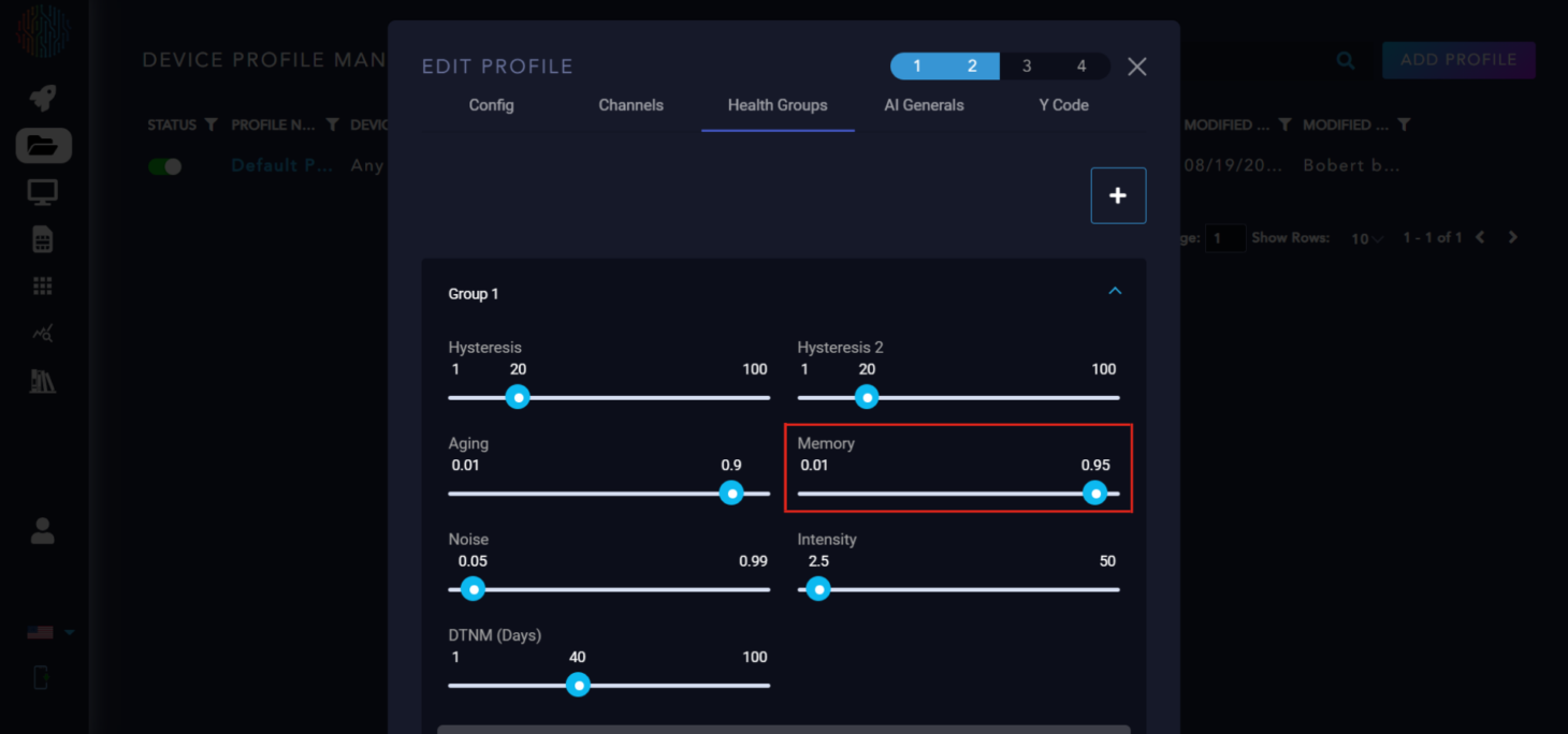
Memory: Coefficient to control how much previous data is remembered (0,1). The closer to one, the more data is considered.
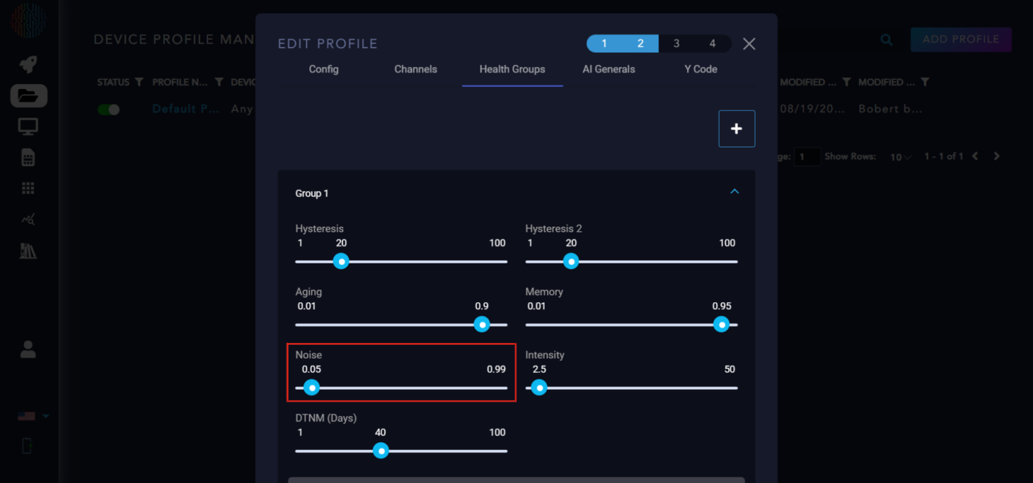
Noise: expected false positive rate (Higher it is, the more abnormal data is ignored).
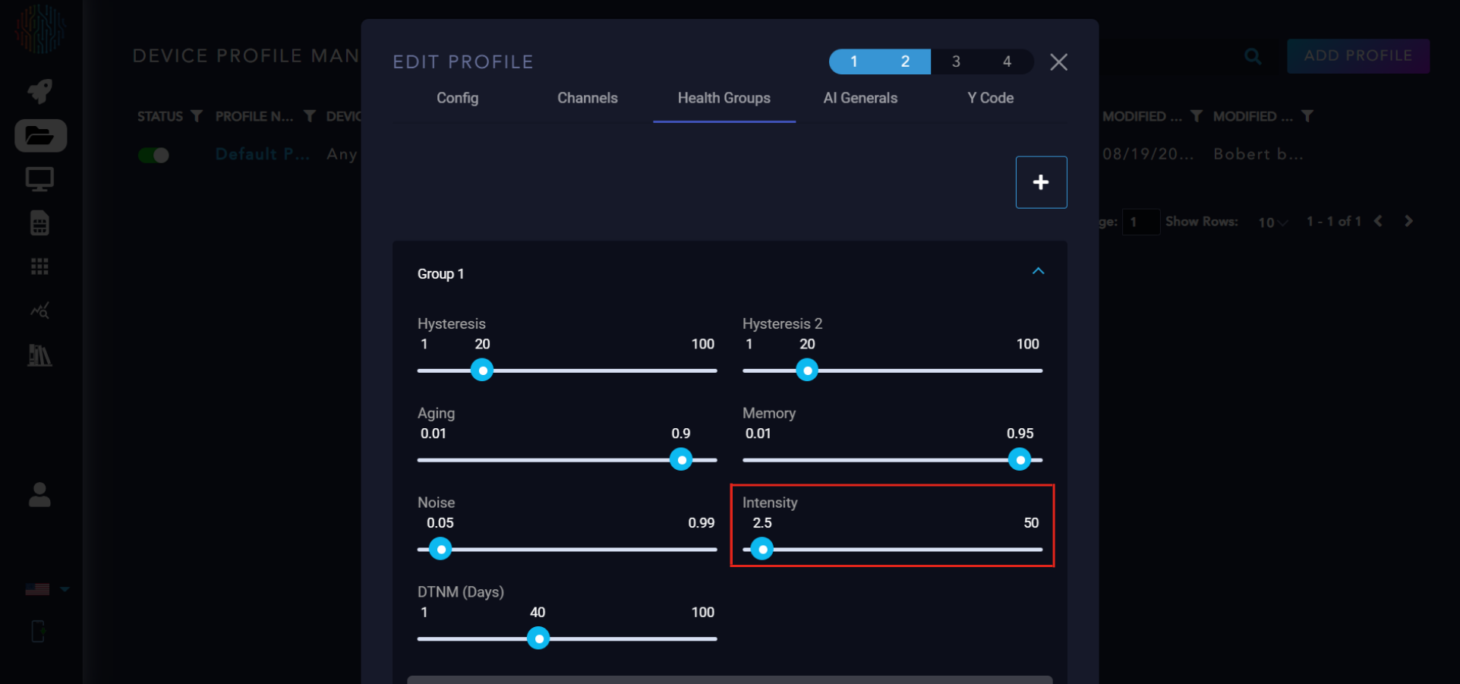
Intensity: Coefficient to control the weight of abnormal channels that are far from the normal bounds. Should not be set higher than the number of total channels.
DTNM: Days to Maintenance is a scaled version of the health score to the nominal maintenance interval and then subtract out the amount of time that has passed since maintenance has occurred.
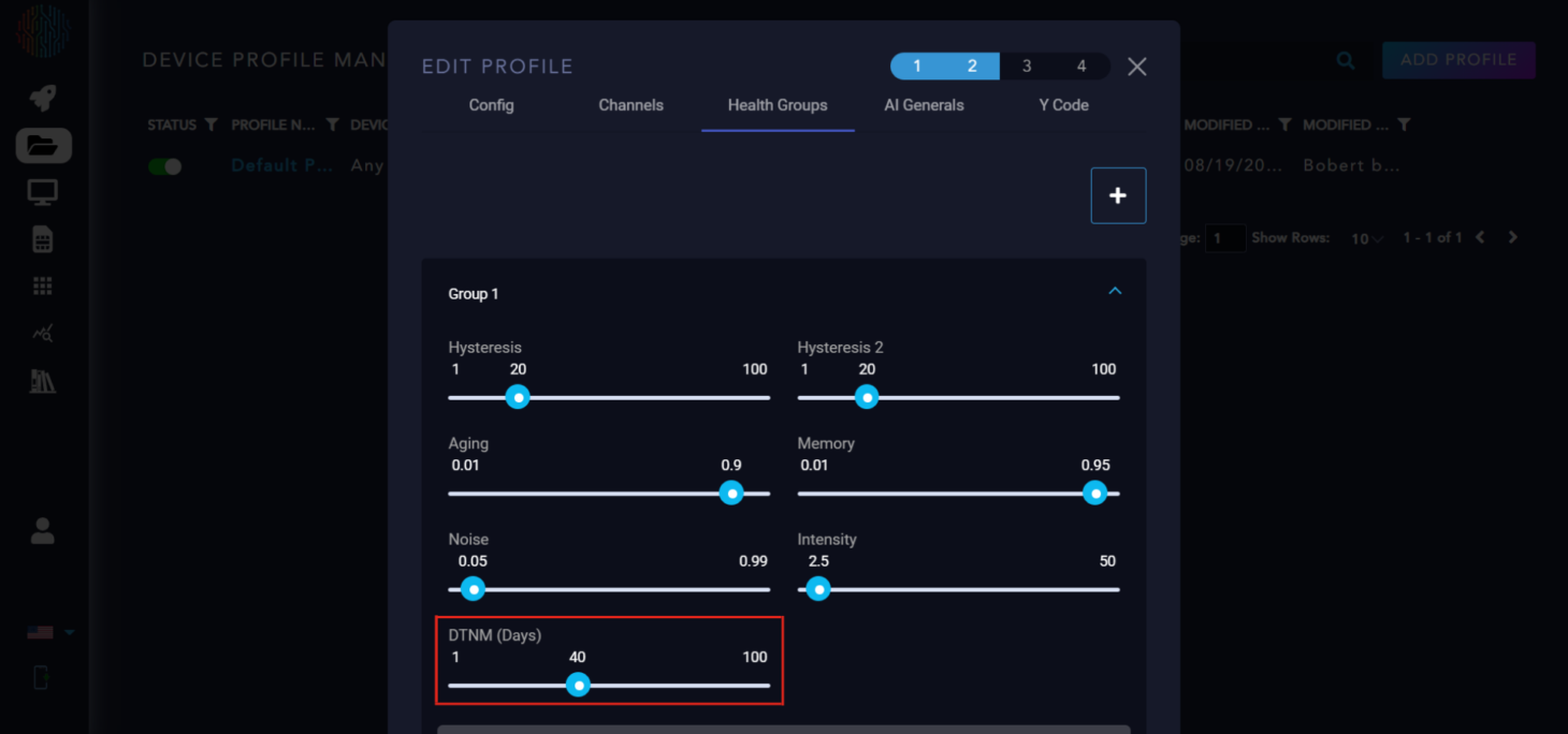
What is Nominal Maintenance Interval (NMI)? Nominal Maintenance Interval (NMI) is provided by the user. This value is the length of the maintenance cycle of the monitored equipment.
Below DTNM you will see three more sliders. RL is number of days of operation expected on the device before it is permanently out of commission. similar to NMI but instead of maintenance, it is for end of life. PdM is the algorithm for predictive maintenance. K is the noise value for remaining life algorithm.
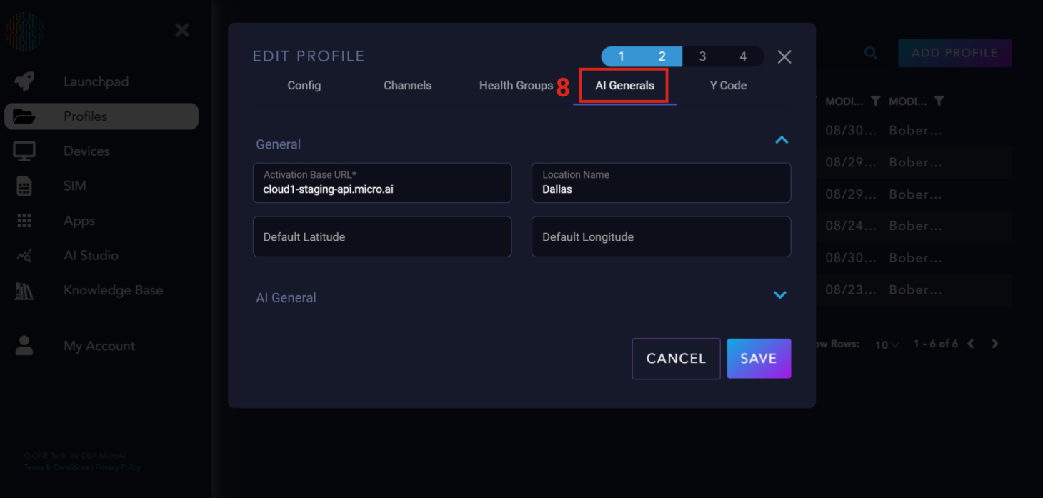
AI Generals#
Next is AI Generals, this is how you would configure the parameters for building your AI model. There are two drops downs, one is called General and the other is AI General. The General dropdown has basic information that you can change but ultimately does not influence the data or the AI in any way. Under AI General there are sliders that are used to tune the AI and we will go over these in detail.
AI General Parameter Explanation#
With the expandable section “AI General Parameter Explanation,” let’s explore the various parameters:
Training Secs controls exactly what it says, the amount of seconds that AI trains for. The default is 300 seconds but can be modified per user discretion.
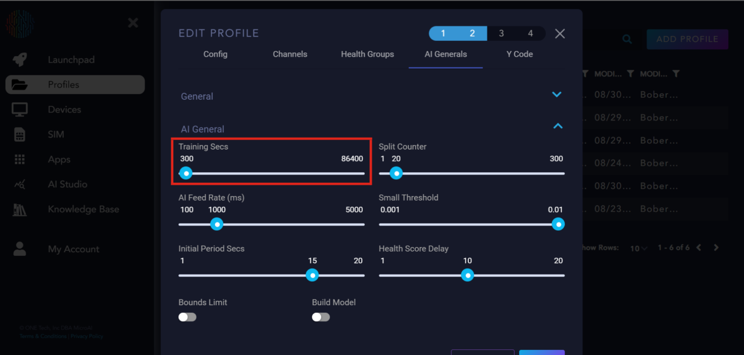
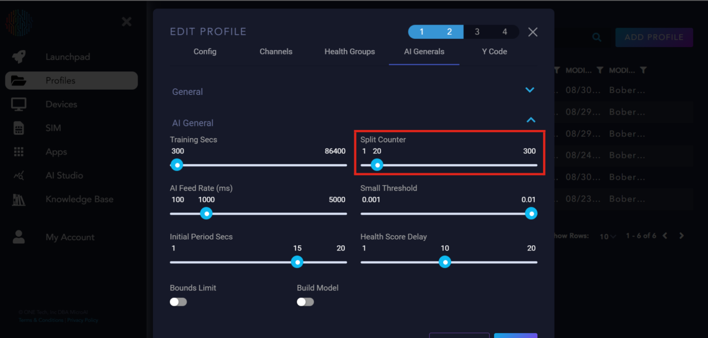
Next to Training secs is Split Counter, this is referred as the period of the device’s behavior.
Important Recommendation: Training secs should be 10 times longer than split counter for ideal training time.
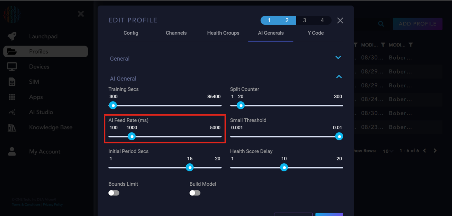
Next is AI Feed Rate. This is the rate that data is accepted by the AI. We recommend 1000 milliseconds but you can modify it to your needs.
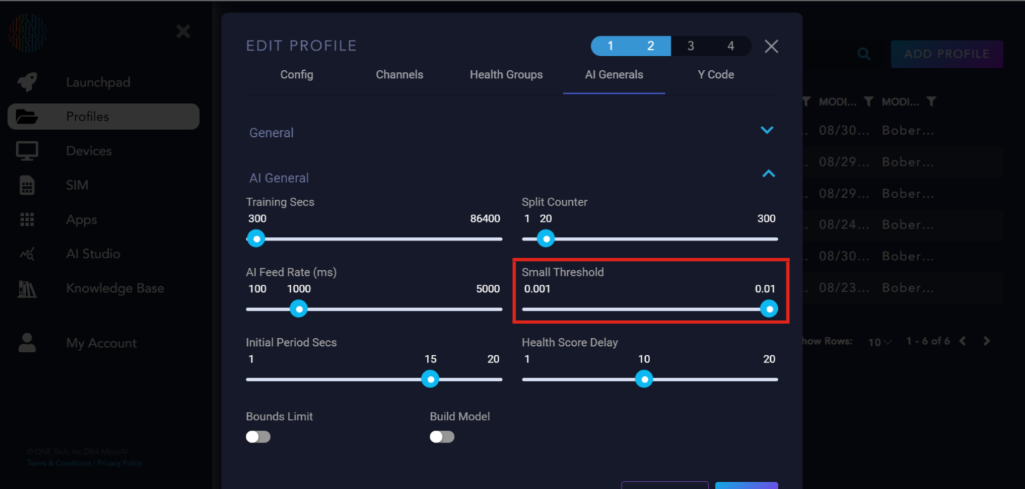
The Small Threshold determines the minimum distance between the upper and lower bounds that they can converge to.
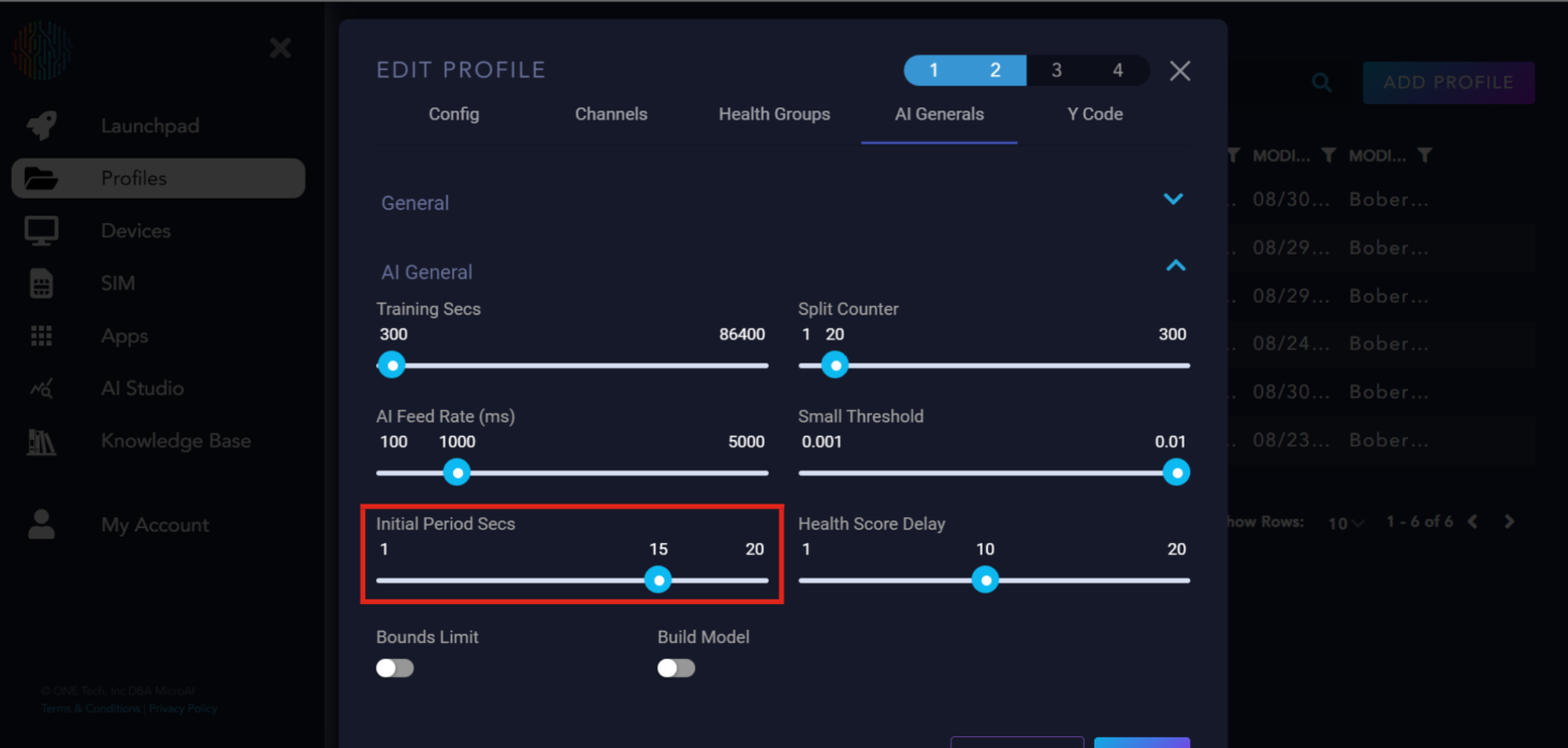
The Initial Period Secs is how long AtomML+™ delays sending data to the AI to begin training or executing.
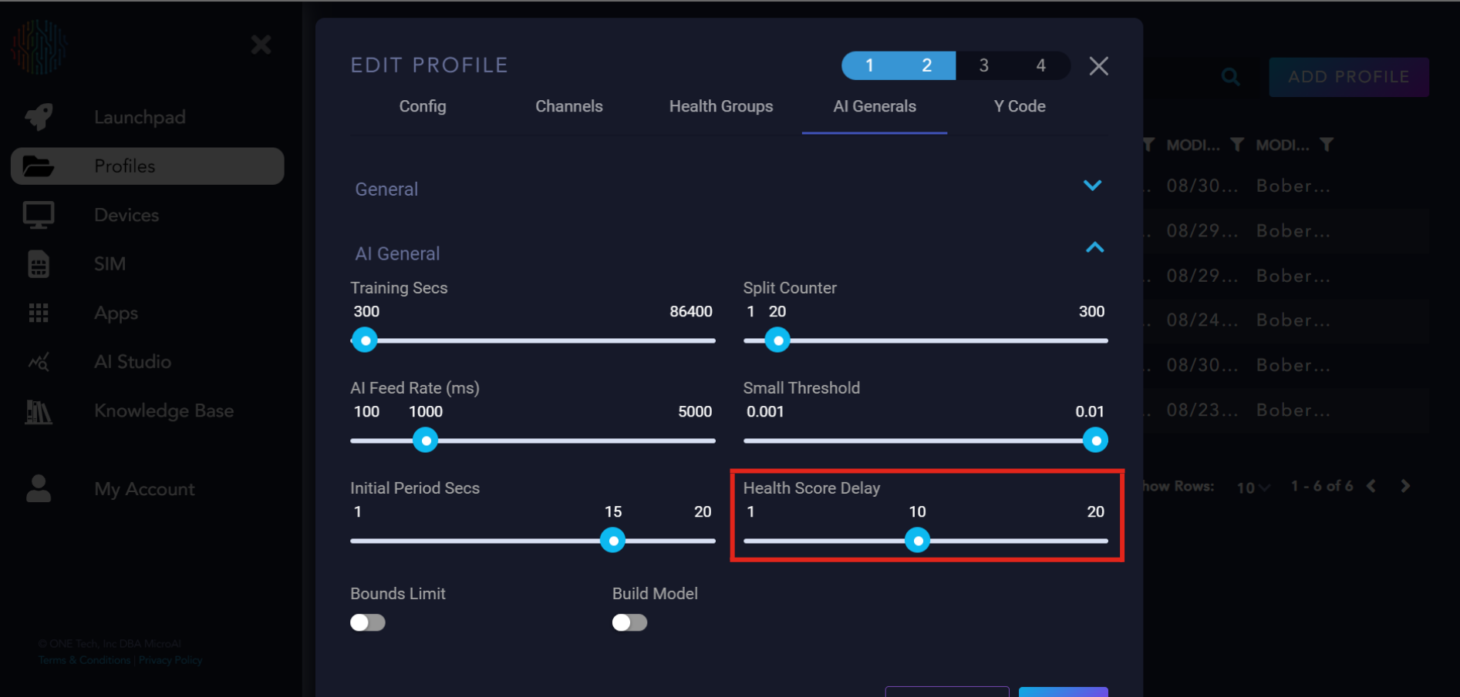
Health Score Delay is the delay in loops between the AI starting and the health score calculation.
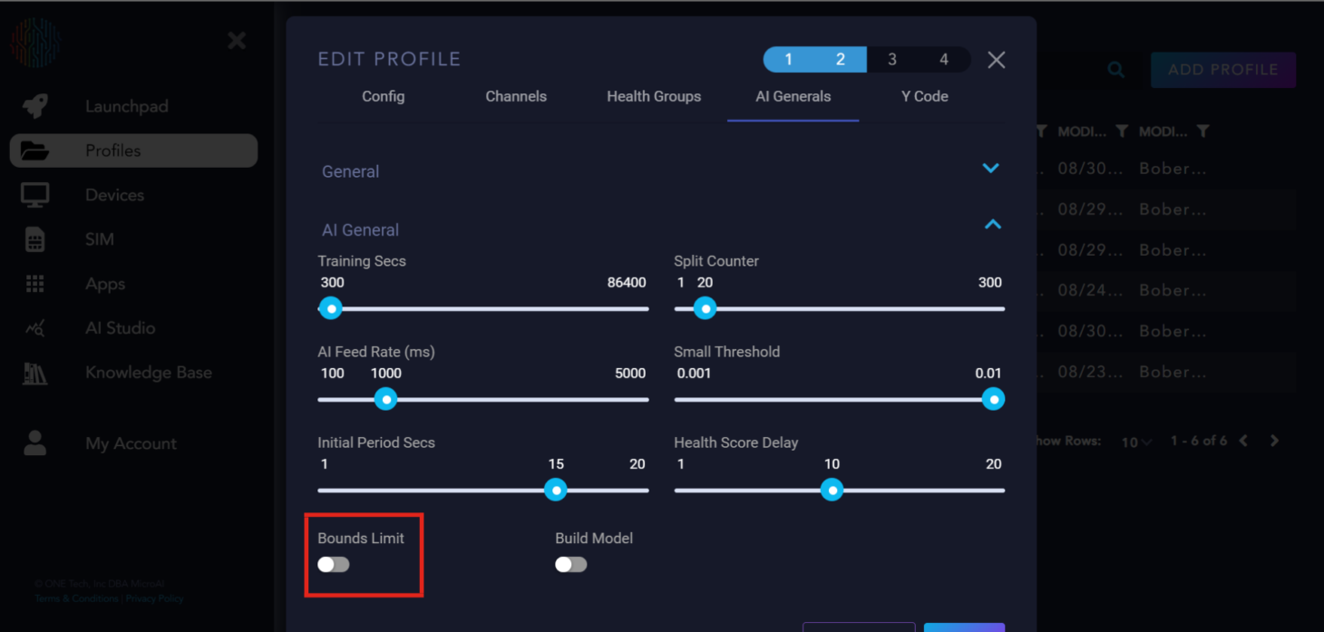
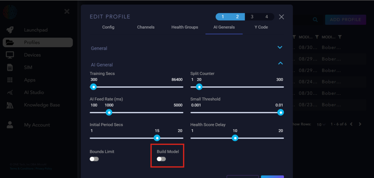
Bounds Limit is a flag for the AI on whether or not it should calculate hard bounds for each channel that the upper and lower bounds can never cross.
Build model is a flag to tell the AI to build the model or not, by default if there is no model available the AI will automatically build one. This button is used if you want to replace the previous AI model with a new one with parameters tuned to the user’s discretion.
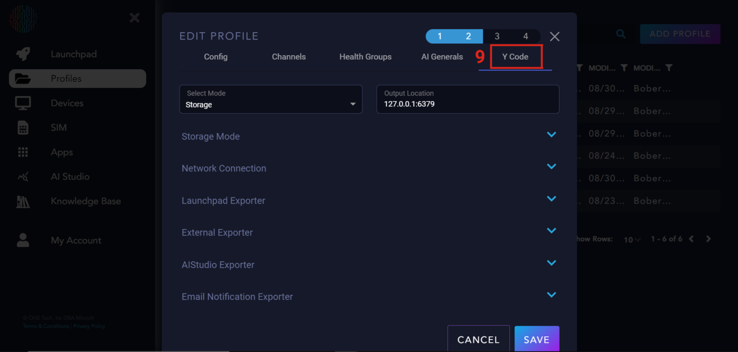
Y Code#
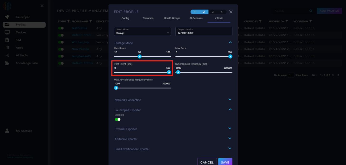
Next is the “Y Code”, there are two modes for Y Code, “Storage” and “Continuous”. The “Continuous” mode will continually send data to the Launchpad for your device. “Storage” mode (the default for AtomML+™) is when we store Asynchronous and Synchronous packets for either a given amount of time or given amount of data (whichever comes first). After the trigger occurs, we send all of the data at one time that we had stored up.
Y Code Parameter Explanation#
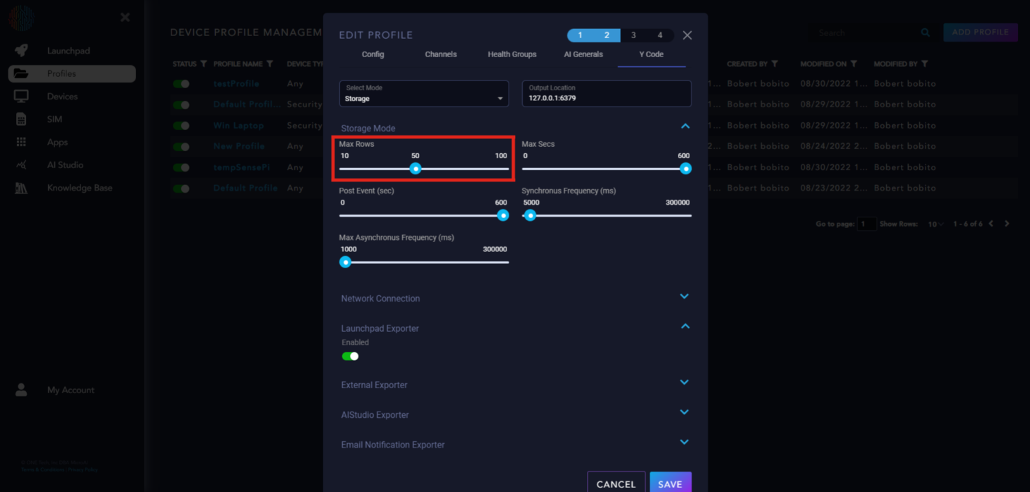
Max Rows is how you set the amount of data. Essentially how many messages to keep stored and to send when the trigger occurs.
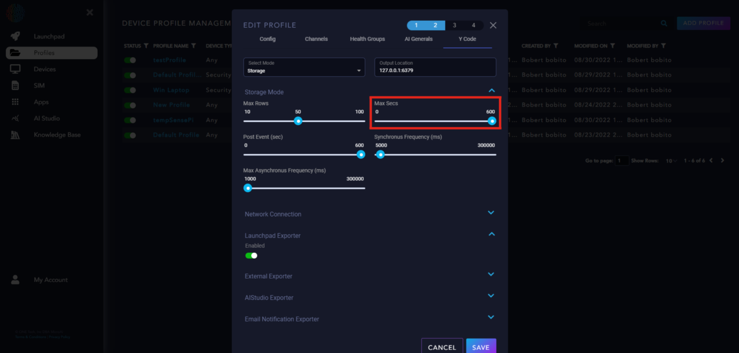
Max Secs is how you set the amount of time. Every loop we check the age of one row (or message if you prefer) and ensure that it is young enough to warrant keeping.
Post Event is the amount of time to operate in continuous mode after the trigger event. This is to give the user the context both before and after the trigger event.
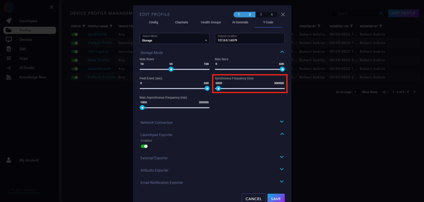
Synchronous Frequency (ms) is the time period at which we generate a sync packet. Should not be run faster than the AIEngine Feed Rate.
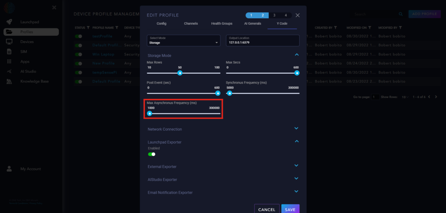
Max Asynchronous Frequency (ms) is the time period at which we generate an async packet. Should not really be run slower than the AIEngine Feed Rate, however, that is not a hard rule that we enforce.
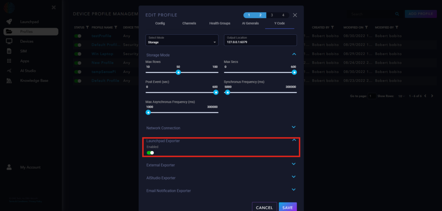
Launchpad Exporter is enabled to send data to Launchpad, we recommend keeping this on.
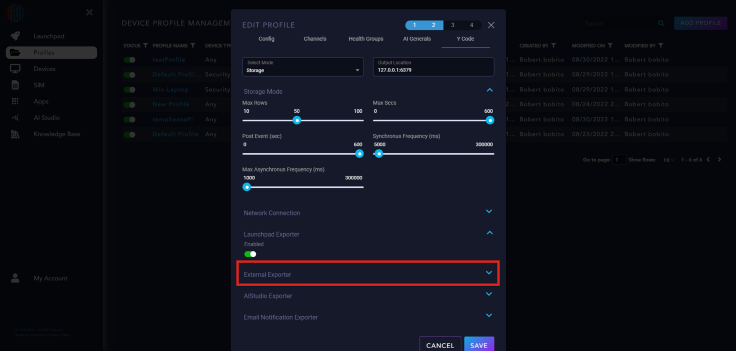
External Exporter only applied to specific use cases, please disregard unless you fall under that category.
AIStudio Exporter is an additional feature that will be added later to Launchpad and will be explained in another section.
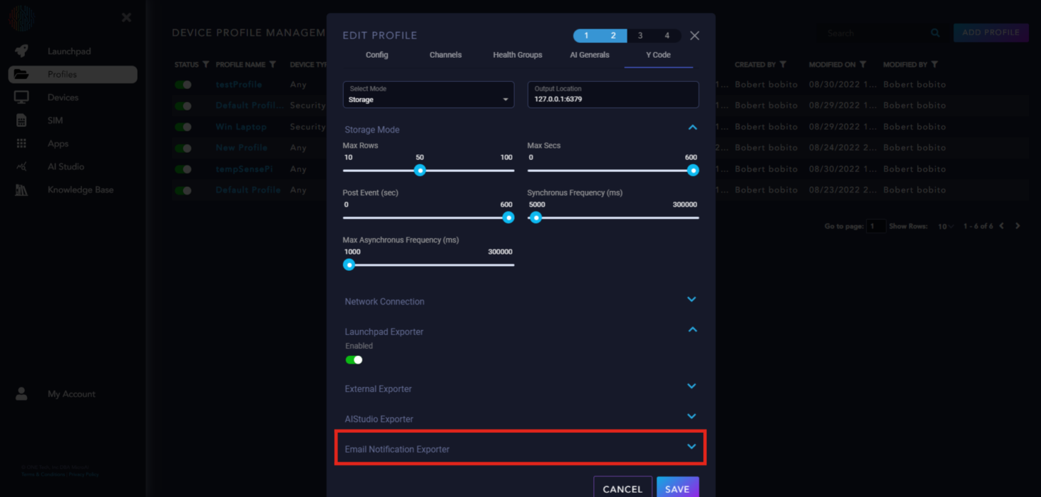
If you would like email notifications for your device, you can set up the “Email Notification Exporter” accordingly.
AtomML+™ on Raspberry Pi using a Temperature Sensor#
Requirements#
One Raspberry Pi with power source.
One MCP9808 Temperature Sensor v1.0.
A breadboard and several connection wires.
An HDMI cord compatible with a Raspberry Pi (May need a mini HDMI), a keyboard and mouse that you can connect to your Raspberry Pi, and a monitor.
Configuring your Raspberry Pi#
Boot up your Raspberry Pi and connect it to the keyboard, mouse, and monitor.
Follow the instructions given to you from the Raspberry Pi on the screen for initial setup.
Press ctr+alt+t to open the terminal. Then type in
sudo raspi-config.In the pop-up window use the arrow keys to go to Interface Options and press enter.
Scroll down to I2 SSH and press enter. The next pop-up window will ask if you would like to enable the SSH server, scroll to <Yes> and click enter.
Press enter on <Ok> on the next pop-up and you will be taken back to the original config screen.
Next, go to Interface and go down to I5 I2C, enable I2C on your raspberry pi and then type in
sudo rebootto save the changes and reboot your Raspberry Pi. This will allow the Raspberry Pi to communicate with the temperature sensor.After clicking <Finish> type
sudo rebootin the terminal to save your configurations and reboot your Raspberry Pi.After rebooting, your Raspberry Pi is correctly configured for this tutorial.
Initializing The Temperature Sensor#
At this point, you should have registered a profile for AtomML+™ on Launchpad. If you do not know how to do this, go back to the top of this page.
Go to your profile and copy the terminal commands for Linux Arm into your Raspberry Pi Terminal. This will download the Zip file for AtomML+™ for Linux Arm.
Unzip the file your downloaded using the terminal command
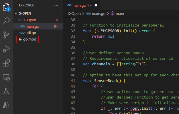
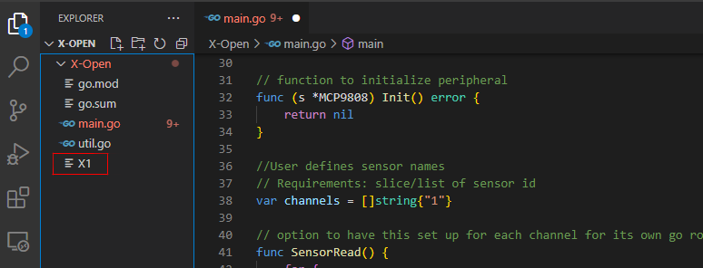
unzip AtomML_Plus_1_0_0.zip. This will create a directory called AtomML_Plus_1_0_0 on your Raspberry Pi.Next, you will find a folder inside the AtomML_Plus_1_0_0 directory called “lib”, inside this folder you will find a folder called “X-Open, This folder contains our open source data ingestion code which is written in Golang. The code that reads in sensor data and sends it to MicroAI can be written in any coding language as long as it connects to the correct server. For this tutorial we will use the Golang version. it should contain two files, main.go and util.go
Next, you need to install Golang on your Raspberry Pi. We will explain how to do this in the following steps.
Go to your terminal and type in the following command:
nano go_installer.sh
Next type in the following command in your .sh file.
export GOLANG="$(curl -s https://go.dev/dl/ | awk -F[\>\<] '/linux-armv6l/ && !/beta/ {print $5;exit}')"
wget https://golang.org/dl/$GOLANG
sudo tar -C /usr/local -xzf $GOLANG
rm $GOLANG
unset GOLANG
Press ctr+s to save your .sh file then ctr+x to exit.
Next, you will type the following command in your terminal to make your .sh executable.
sudo chmod +x go_installer.sh
Now execute your .sh file with the following command.
./go_installer.sh
Golang is now installed on your device, next type in the following command in your terminal.
nano ~/.profile
Go to the bottom of the profile file and type in the following at the very bottom.
PATH=$PATH:/usr/local/go/bin
GOPATH=$HOME/golang
Next type in the following command to add Golang to your source.
source ~/.profile
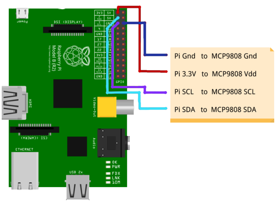
Now we are ready to initialize our temperature sensor, but before that we must connect it to our Raspberry Pi. See the image below to learn how to connect this temperature sensor.
Now go back into the main.go file and follow the code below to initialize the sensor.
package main

import (
    "log"
    "time"

    "periph.io/x/conn/v3/i2c"
    "periph.io/x/conn/v3/i2c/i2creg"
    "periph.io/x/devices/v3/mcp9808"
    "periph.io/x/host/v3"
)

//_______________________USER MODIFICATIONS__________________________//
type MCP9808 struct {
    dev *mcp9808.Dev
}

// New opens a handle to an mcp9808 sensor.
func New(bus i2c.BusCloser) (*MCP9808, error) {
    d, err := mcp9808.New(bus, &mcp9808.DefaultOpts)
    if err != nil {
        return nil, err
    }

    return &MCP9808{
        dev: d,
    }, nil
}

// Function to initialize peripheral
func (s *MCP9808) Init() error {
    return nil
}

// Initialize Sensors
func initializeSensors() {
    // User defines sensor names
    // Requirements: slice/list of sensor id
    channels = []string{"1"} // Sample
    initializeDS(channels)

    // User initializes all sensors
    // Defined as global variables to be called from sensorRead Function
}

// Option to have this set up for each channel for its own go routine at different frequencies
func SensorRead() {
    for {
        // User writes code to gather new sensor data
        // User defined function to get sensor data
        if _, err := host.Init(); err != nil {
            log.Fatal(err)
        }

        // Open default I²C bus. If only one device is connected via i2c then it defaults to that i2c bus
        bus, err := i2creg.Open("")
        if err != nil {
            log.Fatalf("failed to open I²C: %v", err)
        }

        // Create a new temperature sensor.
        sensor, err := mcp9808.New(bus, &mcp9808.DefaultOpts)
        if err != nil {
            log.Fatalln(err)
        }

        measurement, _ := sensor.SenseTemp()
        tempSense := measurement.Celsius()
        // Update Data structure with new sensor values
        sensor_vals := []float64{tempSense}
        updateSensor(sensor_vals)
    }
}

func main() {

    // DS1 is initialized with sensor names as keys
    go subscribeRegister()

    setUpdateRate()
    initializeSensors()

    go SensorRead() // Continuously update DS1 with new data
    go SendData()
    time.Sleep(time.Duration(publishRate) * time.Millisecond)

    loop()
}
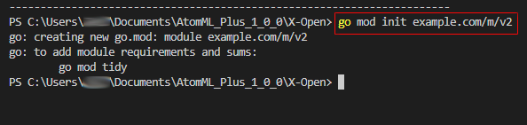
Next, you will insert the command below into your terminal.
go mod init example.com/m/v2
Next, write in the command below into your terminal.
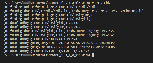
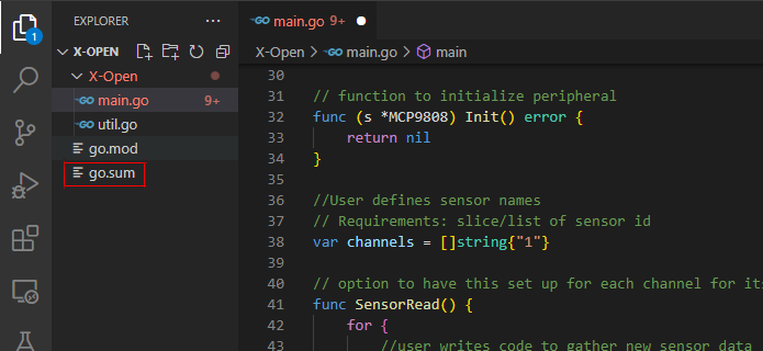
go mod tidy
Now you will build your executable by putting the following command in.
go build

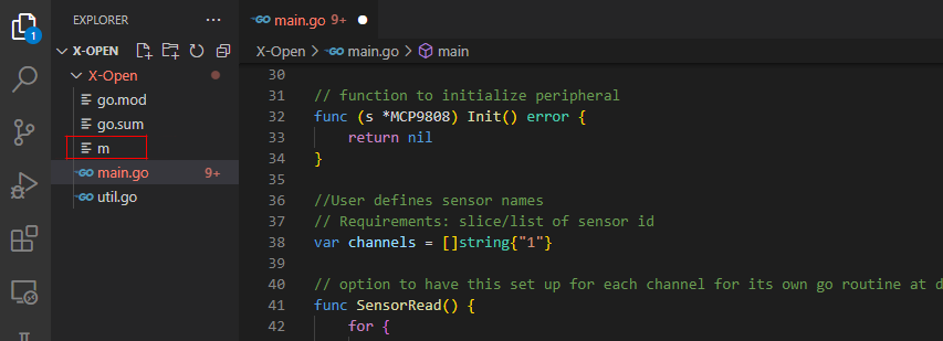
This will create a new file inside of X-Open called “m”, rename this file to “X1” and then transfer “X1” only back into the lib folder inside of the AtomML_Plus_1_0_0 directory on the Raspberry Pi.
Once you have X1 on your Raspberry Pi, go into the bin folder in the AtomML_Plus_1_0_0 directory and type in the following commands in your terminal.
chmod +x main
sudo ./main -MAI_API_KEY=Your Profile API Key
This is how you initialize AtomML+ on a Raspberry Pi with only one channel (temperature sensor) and one group. This will learn the normal behavior of the temperature sensor and then begin monitoring it with our proprietary AI technology.